
Swap-A-Buckle
A 3D printed buckle that’s outward design can be swapped out using a snap fit mechanism.
Use Case and Context
Prompted with an open-ended prompt regarding material exploration and application, I decided to design and make a swappable belt buckle that allows for more creativity and expression in fashion. Intended users include all belt wearers, people who want a more lightweight and low-cost buckle that they could customize. It allows for simple replacement of damaged buckles and easy swap-ability.
Initial Ideation
The crux of the design would be the connection method between the belt connection and the interchangeable design. Based on research and looking at products around me, I explored the concepts of a sliding groove and annular snap fit. I ended up pursuing the annular fit because of familiarity and its 360° engagement.
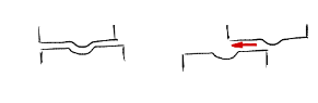
Sliding Groove
(ex. sliding lid)

Annular Fit
(ex. pen cap)
Material Selection and Analysis
PLA
-
Held between 119-184 lbs
-
15.3% elongation
-
Compostable
ABS
-
Held between 209-284 lbs
-
21.6% elongation
-
25% lighter than PLA
From this comparison, I initially settled on ABS, but due to issues with printing and the inability to recycle the material, paired with the concerns of waste given the use case, I switched to PLA.
Proof of Concept


To see whether a snap fit was possible with the materials, or at least a connection using a similar mechanism, I made a quick prototype. It ended up being oversimplified and I did not consider the desired force input and material properties.
This resulted in a snap that was too rigid which did not allow the two pieces to sit flush and required immense force.
FEA Simulation
I then designed a traditional snapfit using YouTube tutorials, but I used FEA simulations to inform the dimensions of the snap fit. In each simulation, I varied dimensions and analyzed the displacement based on a constant input force. The displacement was relevant in achieving a secure fit between the halves without requiring excess force.


Based on the simulations, I added U-slots on the input side to create more affordance in the walls and allow it to flex around the snap, hoping to reduce the required force.

Prototyping


The full annular prototype worked and both surfaces were flush, but the force input to remove the design was slightly more than I desired, so I tested a non-continuous annular snap.

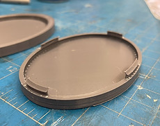

This design met all metrics other than durability as the snaps broke with increased use. Though it decreased the force needed, I decided to stick with the full annular to create a longer lifespan.
Final Desing and CAD


Reflections
-
Allot time for failed prints/manufacturing errors. If I had done this, I think I would've come out with a much more refined design
-
Simulations are a tool, so use them! By simulating the force input I was able to forego a lot of hand calculations or trial and error. Though not perfect, they are a very useful tool