
Universal Stamping Press
I was tasked with creating a stamping machine that must fulfill the following requirements:
-
All components must be connected to one another, other than the inkpad
-
Must use hardware for rotary motion and a single spring with a purely linear load
-
Must stamp a 3.5 x 2’’ business card in the same place each actuation
-
Must be made of 3D and laser cut materials
-
Stamp must move 2’’ minimum
Rapid Prototyping


With this initial prototype I wanted to answer two driver questions:
-
Which rotary mechanism will provide the most uniform and consistent motion?
-
What degree of rotation is ideal for stamping and comfort?
The results of this prototype showed that the crank shaft mechanism was capable of supplying linear motion, but it requires an ample amount of support. And in this model it was found that ~90 degrees of rotation as a user was ideal.
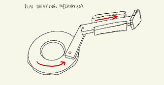
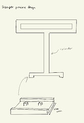
Sketching and Inspiration


Keeping in mind the requirement of 2 inches of motion, I was drawn to a taller design. And aesthetically leaned to a curved design with a circle in the center similar to the image on the side.
In terms of the conversion from rotary to linear motion, I looked at the Scotch Yoke and Crankshaft mechanisms. Then for the resetting requirement, I was initially inspired by the resetting motion of a stapler and slot machine.


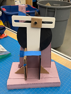
Incorporating Real Materials

The driver questions for the second prototype were:
-
What type of support is needed for the Scotch yoke to move linearly?
-
How should the spring be connected to the mechanism in order for it to reset?
After testing I found that the Scotch Yoke needs plenty of interaction between the supporting walls and the stamp arm to stamp reliably. And also that the spring is overextending when attached to the lever.
This also inspired a new question of whether the Scotch Yoke mechanism could provide enough force to produce a legible stamp.
Back to the Drawing Board
ROTARY-LINEAR MOTION
-
The Scotch Yoke would be the mechanism I commit to in the final prototyping and testing as I had a clearer idea of how to use it.
RESETTING MECHANISM
-
The spring being attached to the lever brought too many complications and would not be the best use of the spring.
-
I also decided to make the lever a part of the wheel to make is a cleaner design

AESTHETICS
-
I committed to the table clock curved shape, but needed to decide what would be laser cut or 3D printed for both aesthetics, functionality, and time management
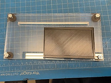
INKPAD
-
I hadn’t tested the inkpad mechanism I had in mind and wanted to simplify it to be efficient
Final Driver Questions
-
Should the inkpad or cardholder be the part sliding?
-
Should my base be three layers or two layers?
-
How and where should my spring be attached?
Component Sketches and CAD


Center Wheel

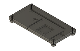
Base


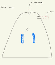
Back Wall


Inkpad Slider

Stamp Arm


Shaft Support
Reaching The Final Assembly

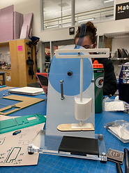
The push to the final assembly was a cycle of real life testing and back to CAD. With each piece of acrylic differing in thickness, I often had to adjust other pieces in correspondence and I relied on a friction fit of the back and base. Looking back, it would hav ebeen smarter to use hardware.
As it came together, I felt that the arm that was connecting to the stamp had some flaws in its placement. However, due to the length of time of a print I was unable to adjust.
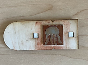
Results and Reflection

This was the outcome of the stamping machine. Due the unequal distribution of force, the top of the jellyfish did not come through. All in all, I am really satisfied with this result and with a readjustment of the stamp arm this could be fixed!

